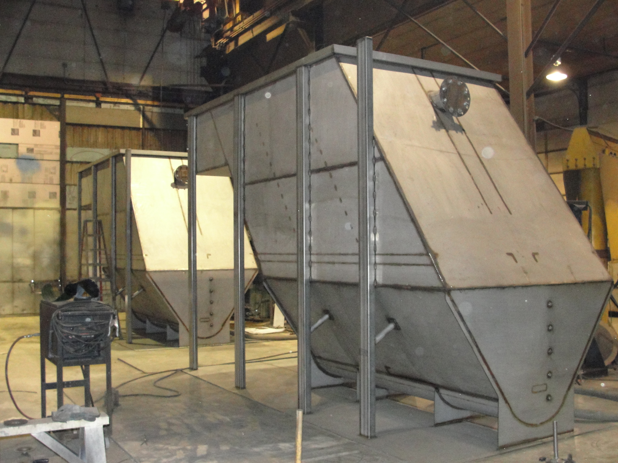
Clarifier – Inclined Plate
Applied Mechanical Technology is an industry leader in industrial wastewater treatment components and systems. Since 1997 we’ve been designing and building industrial equipment and systems for variety of industries.
We design and build all our core technology equipment in-house. Our complete line of equipment includes:
- Oil Water Separators
- DAF Dissolved Air Flotation
- Inclined plate Clarifiers
- Multimedia filters
- Controls Packages
These are the core of our complete systems packages. We complete our systems with strategic OEM relationships for all the other necessary components such as instruments, pumps, valves etc.
As we design and manufacture our core equipment and systems in our own shop we have the flexibility and the ability to configure our systems as needed to meet the most stringent project specifications while exceeding customer’s expectations.

Principal of Operation – Clarifiers
Clarifiers are devices that exploit the laws of physics in that they permit solids to exit via settling in a wastewater stream while the stream is flowing and has velocity. In the simplest terms, we do this by designing a system where the settling rate exceeds the velocity of the flow. This actually works in mirror image to how an Oil Water Separator works (Click to see Oil Water Separator principal of operation). In an Oil Water Separator we calculate the rate of rise, in a clarifier we are concerned with the rate of settling or sedimentation. In both cases we are concerned with the rate being such that the particle (oil or solids) will settle or rise at a rate sufficient to prevent exit before it reaches the effluent section.
In a clarifier we use plates tilted at an 55d steep angle and spaced 2” apart typically. This is done for the same reasons an Oil Water Separator has coalescing media, to increase surface area in a smaller package. As the wastewater flows into the bottom of the plate in an upward flow path to exit the clarifier, the settling solids will land on the plate where they impinge. The solids will gather, increase mass and begin to slide in a down path on the plate toward the sludge chamber. All the while the wastewater flow is in an upward path. This is referred to as laminar flow as there are more than one layer or laminate. It is essential in clarifier design that the settling rate of the particle is greater than the upward velocity in the plate pack or the particle will be carried out.
This is where it gets tricky. Sizing a clarifier is done on a Hydraulic Loading Ratio or HLR that is defined as ratio of GPM/FT2 of projected surface area. Projected surface area is the total area of the tilted plate as projected upward to a flat plane. In other words, a 2x4=8 ft2 plate lying flat projects 8ft2. If the plate is then tilted upward at 55d, the resulting projected surface area less. It is calculated by multiplying the area by the cosine of the angle. The formula is cos of 55d=0.57. Therefore a 2x4=8ft2 plate X 0.57=4.56 ft2 of Projected Surface Area or PSA. This 4.56 x the number of plates is the number that is used to define the FT2 in the HLR.
Typical sizing of a clarifier uses an HLR of between 0.1 and 0.5 gpm/ft2 with 0.25 gpm/ft2 being the benchmark for many applications. The slower the settling rate of the particle, this lower the HLR should be and the faster the settling rate of the particle the higher the HLR should be. Example, a slow settling chromium precipitate floc would use an HLR of between 0.1 and 0.25 gpm/ft2 while a faster settling particle of sand or grit would use a settling rate of 0.3 to 0.5 gpm/ft2.
Settling rate is not the only important consideration. Plate pack velocity is actually equally important of a consideration. If you make a plate pack of 8’ tall plates, at 2” spacing and a clarifier of 250ft2 PSA it will have twice the velocity of a plate pack that is 4’ tall, all other things being equal. We make clarifiers with 4’ tall plates, 6’ tall plates, 7’ and 8’ tall plates. The 6’ tall plate strikes the best balance when it comes to overall design, performance, and cost which is why our 6’ tall plate ClariMore clarifier is the most popular, most cost effective and best performing clarifier configuration. Having a manageable height it tends to fit into rooms better than taller clarifiers, also making it popular.
Clarifier bottom configurations – The bottoms of clarifiers come in many shapes and styles. There are trough styles with augers, pyramidal styles with no augers and circular styles with rotating rakes. We make all but the circular styles. This is due mostly because of cost effectiveness. The cost of the circular style when compared to an external sludge tank makes the decision pretty easy. External sludge tank wins. Our ClariMore clarifier with trough bottom and rotating auger is the best in the business as it is the only one with a half pipe clarifier bottom with a radius that conforms to the auger shape with less than 1/2” gap. Our ClariClear, the economy clarifier for < 100 gpm applications has a half round sludge hopper bottom. Good performance and low cost design. Other brands have a V bottom or a truncated V bottom with a round auger, neither bottoms match the shape of the radius shape of the auger. Truly a square hole with a round peg… Our IPC Clarifier has a pyramidal bottom and is very cost effective as a result however the geometry of the bottom makes for a taller clarifier as a result. If the sludge generated tends to compact then the pyramidal bottom could be problematic.
Clarifier effluent systems also come in several styles. All of our clarifier have stainless steel adjustable saw tooth effluent weirs. The effluent weir adjust is important to compensate for uneven floors and most importantly to achieve completely even flow rates and velocities thru all the plate packs. Even flow rate ensures consistent settling performance and reduces current eddies and short circuiting.
Clarifier Bottom Augers-Rakes if so equipped come in a couple different styles. The auger is a horizontal ribbon screw type auger with converging flights so that one direction rotation appears that the ribbons are converging from outside to the middle. The middle is therefore where the sludge outlet nozzle is positioned. The style, size, pitch and rotation speed are all very important. The wrong auger can cause problems like rat holing, current eddies and can stir the sludge up and liquefy it rather than gently move and thicken it as properly designed auger can do. Our augers are designed based on many years of experience in a variety of different applications. These are the same augers that can be found in our Clarifiers and Oil Water Separator designs.
FFM Flash Floc Mixing Systems are systems that precede Clarifiers and DAF systems. They are the chemical enhancement system that makes good treatment results possible. Without them we could not break emulsions, precipitate metals or agglomerate solids. They are the workhorse before the separator (DAF and Clarifiers are technically separators). If the FFM or its chemistry are not working properly neither will the DAF or Clarifier – period. To see more info on FFM system click here.
We make Clarifiers for a variety of industries including but not limited to:
- Metal plating and conversion coating
- Groundwater remediation
- Solids removal
- Turbidity reduction
- Chemical Etch bath rinse waters
- Bottom fly ash sluice water
- Scrubber water
- Cooling tower water
Typical Options Include:
- Mild steel or stainless steel construction.
- Special coatings for highly corrosive application.
- XP Explosion proof electrical components.
- Bottom sludge augers
- Complete control packages
- Pump skids, inlet, effluent, sludge.
- Chemical dosing and FFM Flash-Floc-Mixing Systems
- Emulsion breaking systems
- Operator platforms.
- Effluent filters
Need a Quote?
Click here for our Application Questionnaire to obtain a quote.
Quality
We use only the highest quality materials, pumps, instruments, valves and controls components to ensure you the heavy duty robust performance you demand in today’s highly competitive market environment. All our systems are built to the highest standards of craftsmanship and are extensively tested throughout the fabrication process. We perform a variety of NDE testing including PQR, UT, XT, full hydro, dye penetrant, ASME pressure testing and of course visual inspections and functional testing both in-shop and in the field.
Controls
Our operator controls interface scheme is the most advanced in the wastewater industry. We offer basic simplified controls to full featured controls systems that use SQL database platforms permitting the generation, archiving and managed all trending and effluent data. Our most advanced controls offer operator input of bench treatability testing that then allow the system.We design and build all our own controls in-house to UL-508A Industrial Control Panel standards with strict conformance to NEC ANSI/NFPA 70 regulations. All panels are built to UL standards and are individually UL certified if required.
Tankwash Systems
Our Industrial Tankwash Division designs and builds Railcar and Tank Trailer Internal wash systems to wash everything from Crude oil to Edible oils, from Chemicals to Corn Starch and everything in between. When you wash an industrial tank, you create an industrial wastewater and we take care of that too.
View pdfs for more information:
Brochure Clari – Clear
Brochure Clari – IPC
Brochure Clari- More
Brochure Controls – WW System